Wiring diagram, howtos and diy wiki blog with HD images
Home
› Main Electrical Panel Wiring Diagram / How To Add A Subpanel With Pictures Wikihow / Everything you need to know about the point of entry for a home's electricity, from an electric panel.
Main Electrical Panel Wiring Diagram / How To Add A Subpanel With Pictures Wikihow / Everything you need to know about the point of entry for a home's electricity, from an electric panel.
Main Electrical Panel Wiring Diagram / How To Add A Subpanel With Pictures Wikihow / Everything you need to know about the point of entry for a home's electricity, from an electric panel.. Please download these electrical sub panel wiring diagram by using the download button, or right visit selected image, then use save image menu. Residential electric wiring diagrams are an important tool for installing and testing home electrical circuits and they will also help you understand how electrical devices are wired and how various electrical devices and controls operate. A wiring diagram is a simple visual representation of the physical connections and physical layout of an electrical system or circuit. Wiring diagrams help technicians to see the way the controls are wired to the system. For example, how the horns are powered and connected to the controller on your steering wheel.
Residential electric wiring diagrams are an important tool for installing and testing home electrical circuits and they will also help you understand how electrical devices are wired and how various electrical devices and controls operate. A wiring diagram is a simplified conventional pictorial representation of an electrical circuit. Wiring diagrams in 1950 there were approximately 200 electrical circuits in a truck. So there are three electrical panels inside this riser room. Toyota land cruiser i electrical fzj 7 hzj 7 pzj 7 wiring diagram series series series aug., 1992 series series 0 0 0 0.
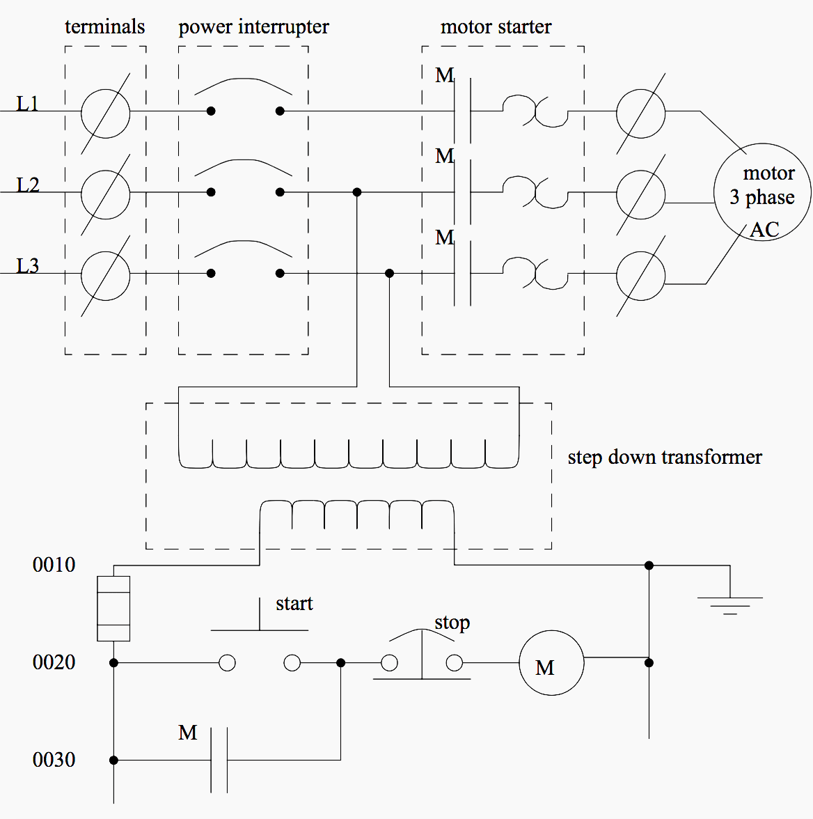
Basic Electrical Design Of The Plc Panel Wiring Diagram Eet 2021 from i0.wp.com A wiring diagram is a simplified conventional photographic depiction of an electric circuit. Type of wiring diagram wiring diagram vs schematic diagram how to read a wiring diagram: Everything related to an electrical system can. It shows how the electrical wires are interconnected and can also show where fixtures and components may be connected to the system. Power lines coming from your local electrical company come in from the pole transformer to a mask on the home or they may come in. Service entry wiring electric meter main panel wiring outlets lights switches. When and how to use a wiring. Interconnecting wire routes may be shown approximately.
It shows how the electrical wires are interconnected and can also show where fixtures and components may be connected to the system.
Electrical diagrams and schematics, electrical single line diagram, motor symbols, fuse symbols, circuit breaker symbols, generator symbols. This is what we draw using autocad electrical. So there are three electrical panels inside this riser room. The electrical design for each machine must include at least the following components. Electrical panel wiring diagrams are used to outline each device, as well as the connection between the devices found within an electrical panel. Each part ought to be set and connected with different parts in specific manner. 200 amp main panel wiring diagram electrical panel box diagram. Interconnecting wire routes may be shown approximately. Electrical wiring diagrams of a plc panel. Control wiring diagram of star delta starter pdf. In case the fan doesn't function or whether or not it wobbles, you may need to look at the parts and connections again. Each page of this wiring diagram shows the exact wiring for different sections of this control panel. Residential electric wiring diagrams are an important tool for installing and testing home electrical circuits and they will also help you understand how electrical devices are wired and how various electrical devices and controls operate.
It shows how the electrical wires are interconnected and can also show where fixtures and components may be connected to the system. The electrical panel wiring diagram above displays an example of a circuit breaker as well as multiple fuses that protect variable frequency drives. All the wiring that you see in the panel is done based on the wiring diagram. Schematic electrical wiring diagrams are different from other electrical wiring diagrams because they show the flow through the circuit rather than the physical layout of the least useful of the main electrical wiring diagrams is the pictorial diagram and for this reason alone, it's not commonly used. Service entry wiring electric meter main panel wiring outlets lights switches.
Tesla Institute School Of Electrical Engineering Electronics Automation And Computer Technology Wiring Diagrams In Electrical Control Panels from www.tesla-institute.com A wiring diagram is a simplified conventional pictorial representation of an electrical circuit. The main electrical panel can also be called the electrical service panel or electrical distribution panel and is where all wiring through out the home connect. Shop circuit breakers breaker boxes fuses at lowes. The electrical panel wiring diagram above displays an example of a circuit breaker as well as multiple fuses that protect variable frequency drives. Interconnecting wire routes may be shown approximately. I called up electrical experts to upgrade my electrical wiring, so he installed mcb at mains power supply, and did all the necessary actions with great perfectness. Each part ought to be set and connected with different parts in specific manner. White wires marked with a black circle are hot not neutral.
Assortment of double wide mobile home electrical.
Each page of this wiring diagram shows the exact wiring for different sections of this control panel. Collection of electrical panel wiring diagram. A wiring diagram is a sort of schematic which uses abstract pictorial symbols to reveal all the affiliations of components in a system. A wiring diagram may include the wiring of a vehicle. Power lines coming from your local electrical company come in from the pole transformer to a mask on the home or they may come in. Electrical diagrams and schematics, electrical single line diagram, motor symbols, fuse symbols, circuit breaker symbols, generator symbols. Click on the image to enlarge, and then save it to your computer by right clicking on the image. Interconnecting wire routes may be shown approximately. A wiring diagram is a simplified conventional photographic depiction of an electric circuit. Everything you need to know about the point of entry for a home's electricity, from an electric panel. Many people can see and understand schematics generally. So there are three electrical panels inside this riser room. Wiring diagram 200 amp meter base wiring diagram unique service.
A wiring diagram is a simplified conventional pictorial representation of an electrical circuit. Everything related to an electrical system can. Residential electric wiring diagrams are an important tool for installing and testing home electrical circuits and they will also help you understand how electrical devices are wired and how various electrical devices and controls operate. Service entry wiring electric meter main panel wiring outlets lights switches. All the wiring that you see in the panel is done based on the wiring diagram.
Basic Electrical Design Of A Plc Panel Wiring Diagrams Eep from electrical-engineering-portal.com Wiring diagrams help technicians to see the way the controls are wired to the system. Square d homeline 100 amp 12 space 24 circuit indoor main breaker. Interconnecting wire routes may be shown approximately. Each page of this wiring diagram shows the exact wiring for different sections of this control panel. The electrical panel wiring diagram above displays an example of a circuit breaker as well as multiple fuses that protect variable frequency drives. Control wiring diagram of star delta starter pdf. All the wiring that you see in the panel is done based on the wiring diagram. Symbols you should know wiring diagram examples with the use of different symbols, an electrical wiring diagram mainly consists of three main types.
Electrical diagrams and schematics, electrical single line diagram, motor symbols, fuse symbols, circuit breaker symbols, generator symbols.
Now electronic controls applied to every vehicle system and networked electrical systems have added far more complexity to todays vehicles. Figure 10 provides an example of the relationship between a schematic diagram (figure 10a) and a wiring diagram (figure 10b) for an air drying unit. For example, how the horns are powered and connected to the controller on your steering wheel. A wiring diagram is a simplified conventional photographic depiction of an electric circuit. The electrical design for each machine must include at least the following components. For electrical panel wiring diagram. Type of wiring diagram wiring diagram vs schematic diagram how to read a wiring diagram: Interconnecting wire routes may be shown approximately. In an industrial setting a plc is not simply plugged into a wall socket. In 1950, the main interest was the starting, ignition and lighting circuits. A wiring diagram is a simplified conventional pictorial representation of an electrical circuit. A wiring diagram is a simple visual representation of the physical connections and physical layout of an electrical system or circuit. Square d homeline 100 amp 12 space 24 circuit indoor main breaker.