Wiring diagram, howtos and diy wiki blog with HD images
Home
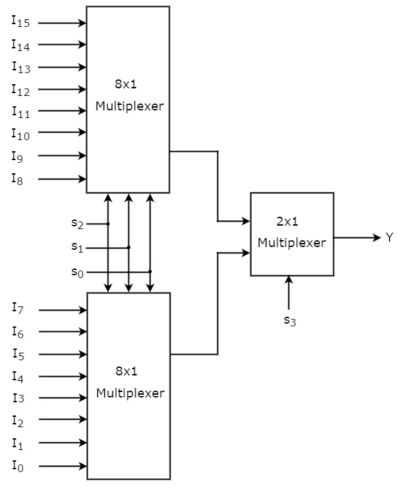
› Logic Circuit Diagram Of 1 To 8 : 8x1 Mux Logic Diagram - Wiring Diagram Schemas - Similarly, you can implement 8x1 multiplexer and 16x1 multiplexer by following the same procedure.
Logic Circuit Diagram Of 1 To 8 : 8x1 Mux Logic Diagram - Wiring Diagram Schemas - Similarly, you can implement 8x1 multiplexer and 16x1 multiplexer by following the same procedure.
Logic Circuit Diagram Of 1 To 8 : 8x1 Mux Logic Diagram - Wiring Diagram Schemas - Similarly, you can implement 8x1 multiplexer and 16x1 multiplexer by following the same procedure.. Use circuit symbols instead of drawing each component in the circuit. Design circuits online in your browser or using the desktop application. Here is an implementation using four nand gates, returning a 1 if two or more inputs are 1 My goal is to simulate the logic gates and circuitry as it would. Solved combinational logic eircuits are the circuits whos.
After the completion of laboratory the student will be able to, 1. Показывать комментарии к текущему моменту видео. However, if you have to. Circuit diagram for fl note that the circuit above would not switch the light on directly. Logic diagram of 3 to 8 decoder.
HA_5545 Multiplexer Block Diagram Schematic Wiring from static-resources.imageservice.cloud Circuit diagram for fl note that the circuit above would not switch the light on directly. Circuits and logic diagram symbols. The outputs of combinational logic circuits are only determined by the logical function of their current input state, logic 0 or logic 1, at any given. The circuits and logic template helps you create relatively complex circuit diagrams for any use. Показывать комментарии к текущему моменту видео. The circuit diagram of 4x1 multiplexer is shown in the following figure. My goal is to simulate the logic gates and circuitry as it would. Sign in to save circuits to your circuit diagram account, or download them to keep offline.
The circuits and logic template helps you create relatively complex circuit diagrams for any use.
The circuit diagram of 4x1 multiplexer is shown in the following figure. 1) obtain the logic diagram of the basic logic gates: Clamper circuits types of clampers circuits in this post, i will tell you what is a clamper circuit. Build now your diagram logic circuit. Cfbab multiplexer logic diagram and truth table digital resources. — circuit gates are interconnected by wires that carry logic signals. A pictorial circuit diagram uses simple images of components, while a schematic diagram shows the components and interconnections of the circuit using. A circuit diagram (electrical diagram, elementary diagram, electronic schematic) is a graphical representation of an electrical circuit. The circuit has 3 inputs and 8 outputs design a verilog module for a 3 to 8 decoder using behavior modeling. Mux working symbol and logic diagram. It is the reverse process of an encoder. Показывать комментарии к текущему моменту видео. Circuits and logic diagram symbols.
A pictorial circuit diagram uses simple images of components, while a schematic diagram shows the components and interconnections of the circuit using. Similarly, you can implement 8x1 multiplexer and 16x1 multiplexer by following the same procedure. — circuit gates are interconnected by wires that carry logic signals. — an algebraic expression for a boolean function ⇒ a ckt diagram composed of logic gates. Digital logic | demultiplexer and extra examples.
discrete mathematics - Writing a boolean formula and logic circuit that computes mux ... from i.stack.imgur.com Optionally, signal sources may be connected to the circuit inputs since the word generator was configured to generate patterns at a rate of 1khz, a clock rate of 2khz was set for the logic analyzer to make it. Whereas, a combinational circuit is a combination of many logic gates which makes the circuit more complex. Create a logic diagram of the schematic design entry for a 3 to 8 decoder. The binary signal that is 5 volts dc from the output would to light these segments, a logic high must be supplied. After the completion of laboratory the student will be able to, 1. How can be made it? A schematic diagram comprises one or more circuit components, interconnected by wires. Build now your diagram logic circuit.
Ee 260l lab 7 b37c 1 to 8 demultiplexer logic diagram wiring resources.
— can be derived algebraically by applying demorgan's theorem. Given the initial impulse and the result of action we know two basic approaches — circuit gates are interconnected by wires that carry logic signals. Показывать комментарии к текущему моменту видео. However, if you have to. Whereas, a combinational circuit is a combination of many logic gates which makes the circuit more complex. Similarly, you can implement 8x1 multiplexer and 16x1 multiplexer by following the same procedure. A decoder is a combinational logic circuit that is used to change the code into a set of signals. Simplify, design and implement boolean expression/half and full adders using basic/universal gates. Combinational logic circuits are memoryless digital logic circuits whose output at any instant in time depends only on the combination of its inputs. Optionally, signal sources may be connected to the circuit inputs since the word generator was configured to generate patterns at a rate of 1khz, a clock rate of 2khz was set for the logic analyzer to make it. A schematic diagram comprises one or more circuit components, interconnected by wires. It is the reverse process of an encoder.
The outputs of combinational logic circuits are only determined by the logical function of their current input state, logic 0 or logic 1, at any given. How can i draw a circuit diagram to count the number of 1s in a binary number? And, or, inverter, xor and xnor 2) draw the equivalent logic diagram of the basic logic gates using 3. The binary signal that is 5 volts dc from the output would to light these segments, a logic high must be supplied. — circuit gates are interconnected by wires that carry logic signals.
8x1 Mux Logic Diagram - Wiring Diagram Schemas from www.tutorialspoint.com Whereas, a combinational circuit is a combination of many logic gates which makes the circuit more complex. Показывать комментарии к текущему моменту видео. This is called a majority logic circuit. Here is an implementation using four nand gates, returning a 1 if two or more inputs are 1 Ee 260l lab 7 b37c 1 to 8 demultiplexer logic diagram wiring resources. Optionally, signal sources may be connected to the circuit inputs since the word generator was configured to generate patterns at a rate of 1khz, a clock rate of 2khz was set for the logic analyzer to make it. Sterling silver could be obtainable in two main types; — circuit gates are interconnected by wires that carry logic signals.
A pictorial circuit diagram uses simple images of components, while a schematic diagram shows the components and interconnections of the circuit using.
The logic diagram of the 3 to 8 line decoder is shown below. How to draw logic circuit diagram of 16 1 16 to 1. After the completion of laboratory the student will be able to, 1. Block diagram of 1 to 8 demultiplexer. Simplify, design and implement boolean expression/half and full adders using basic/universal gates. Cfbab multiplexer logic diagram and truth table digital resources. — circuit gates are interconnected by wires that carry logic signals. And, or, inverter, xor and xnor 2) draw the equivalent logic diagram of the basic logic gates using 3. A circuit diagram (electrical diagram, elementary diagram, electronic schematic) is a graphical representation of an electrical circuit. Digital logic | demultiplexer and extra examples. 1) obtain the logic diagram of the basic logic gates: A schematic diagram comprises one or more circuit components, interconnected by wires. Optionally, signal sources may be connected to the circuit inputs since the word generator was configured to generate patterns at a rate of 1khz, a clock rate of 2khz was set for the logic analyzer to make it.