Wiring diagram, howtos and diy wiki blog with HD images
Home
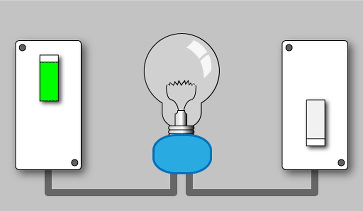
› Single Pole Switch Wiring Diagram : How To Wire A Pilot Light Switch 2 And 3 Way Wiring - In this diagram we show how the wires are attached to the switch and the light.
Single Pole Switch Wiring Diagram : How To Wire A Pilot Light Switch 2 And 3 Way Wiring - In this diagram we show how the wires are attached to the switch and the light.
Single Pole Switch Wiring Diagram : How To Wire A Pilot Light Switch 2 And 3 Way Wiring - In this diagram we show how the wires are attached to the switch and the light.. Circuit layout, wire economy and other factors will determine how the wiring is installed. Either 14/2 with ground (wg) for 15 amp circuits or 12/2wg for 20 amp circuits. Cs220 2gy 5604 2 1288 3032 2e plr leviton 20 amp commercial double pole toggle switch white r52 0csb2 2ws the 2w 120 277v side wired gexpro 15 combination r62 05224 5628 30 grade heavy duty pilot light red 05634 0ws distributors and comparison octopart component. By admin | october 21, 2017. Featuring wiring diagrams for single pole wall switches commonly used in the home.
One trick that we use is to printing a similar wiring plan off twice. But before you start the wiring works. Receptacle on line side, single pole switch on load side. Bend the end into a loop, using the wire strippers or needle. The difference between a single and 2 pole switch is a 2 pole is nothing more than two single pole switches built into one device.
How To Wire A 3 Way Switch Wiring Diagram Dengarden from images.saymedia-content.com Insulated wires connected to three screws. Watch this video to learn how to install the 1451, decora® 5601 and renu re151 single pole switches.if you're ever unsure about wiring a device, please consu. Then strip about 3/4 inch of insulation, using wire strippers. • attach wallplate (sold separately) and restore power. This is too simple and easy connection and you can wire it just like a one way switch. Single pole switch diagram #2 this switch wiring diagram shows the power source starting at the fixture box. The diagrams below show the various options. • carefully position all wires to provide room in wall box for switch.
Today i will show you the single pole mcb connection diagram and video tutorial.
Connect wires per wiring diagram as follows. Proper wiring for a single pole switch that controls a light from the center of a circuit. Today i will show you the single pole mcb connection diagram and video tutorial. But before you start the wiring works. Sometimes it is handy to have an outlet controlled by a switch. • remove insulation from each wire in the wall box as shown. When you make use of your finger or stick to the circuit along with your eyes, it's easy to mistrace the circuit. I will try my best to tech you about the electrical wiring. The diagrams below show the various options. • attach wallplate (sold separately) and restore power. Explanation of wiring diagram #1 switch wiring shows the power source (power in) starts at the switch box. In which i shown the complete method of wiring of single pole mcb connection. Blank cover on line side, single pole switch on load side.
In other words, it's like two simple switches controlled by a single actuator. Featuring wiring diagrams for single pole wall switches commonly used in the home. Diagrams coupled with some instructions to help you on your way to wiring a single switch. Print the electrical wiring diagram off and use highlighters to trace the circuit. Connect wires per wiring diagram as follows.
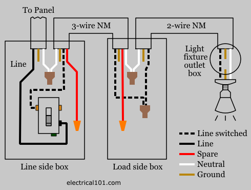
Convert 3 Way Switches To Single Pole Electrical 101 from www.electrical101.com Step 4 connect wires per wiring diagram as follows: • remove insulation from each wire in the wall box as shown. Want to turn a lamp on with a light switch? When you make use of your finger or perhaps follow the circuit with your eyes, it's easy to mistrace the circuit. • attach wallplate (sold separately) and restore power. Flip the switch on and electricity flows. Two single pole switches on separate circuits. I will try my best to tech you about the electrical wiring.
Step by step instructions on how to wire a switched outlet.
With easy to follow diagrams and instructions, you can have that convenience in no time. The source is at sw1 and the hot wire is connected to one of the terminals there. When you make use of your finger or perhaps follow the circuit with your eyes, it's easy to mistrace the circuit. Receptacle on line side, single pole switch on load side. Explanation of wiring diagram #1 switch wiring shows the power source (power in) starts at the switch box. Single pole contactor wiring diagram wiring diagram is a simplified all right pictorial representation of an electrical circuit it shows the components of the circuit as simplified shapes and the capability and signal contacts in the midst of the devices. • carefully position all wires to provide room in wall box for switch. By admin | october 21, 2017. With this sort of an illustrative manual, you'll have the ability to troubleshoot, stop, and total your assignments easily. 5335 outlet single pole tools needed to install switch: Today i will show you the single pole mcb connection diagram and video tutorial. When the switch is off, the connection between these two wires is broken, and the fixture gets no electricity. Inspect the end of each wire.
Single pole switch on line side (left side of diagram), blank cover on load side (to light). Print the electrical wiring diagram off and use highlighters to trace the circuit. If the wiring in the wall box does not resemble any of these configurations, consult a qualified electrician. Flip the switch on and electricity flows. One trick that we use is to printing a similar wiring plan off twice.
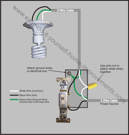
Light Switch Wiring Diagram from www.easy-do-it-yourself-home-improvements.com A single pole switch is easy to understand. Mar 09, 21 09:56 pm. The source is at sw1 and the hot wire is connected to one of the terminals there. This is too simple and easy connection and you can wire it just like a one way switch. Inspect the end of each wire. Either 14 2 with ground wg for 15 amp circuits or 12 2wg for 20 amp circuits. 5335 outlet single pole tools needed to install switch: Connect wires per wiring diagram as follows.
Featuring wiring diagrams for single pole wall switches commonly used in the home.
Print the electrical wiring diagram off plus use highlighters to be able to trace the routine. If the wiring in the wall box does not resemble any of these configurations, consult a qualified electrician. Then strip about 3/4 inch of insulation, using wire strippers. Featuring wiring diagrams for single pole wall switches commonly used in the home. Either 14 2 with ground wg for 15 amp circuits or 12 2wg for 20 amp circuits. Circuit electrical wiring enters the switch box A single pole switch is easy to understand. If the wire end is in poor condition, trim off the bare end; Blank cover on line side, single pole switch on load side. Circuit layout, wire economy and other factors will determine how the wiring is installed. Single pole switch on line side (left side of diagram), blank cover on load side (to light). Need help wiring a 3 way switch? Single pole multiple light switch wiring diagram.